Tuesday, 15 December 2015

OPERATION SYSTEM STOPWATCH WITH LAPTIMES

By using Silicon Lab Toolstick850, a stopwatch is a handheld timepiece designed to measure the amount of time elapsed from a particular time when activated to when the piece is deactivated. A large digital version of a stopwatch designed for viewing at a distance, as in a sports stadium, is called a stop clock.

         The timing functions are traditionally controlled by two buttons on the case. Pressing the top button starts the timer running, and pressing the button a second time stops it, leaving the elapsed time displayed. A press of the second button then resets the stopwatch to zero. The second button is also used to record split times or lap times. When the split time button is pressed while the watch is running, the display freezes, allowing the elapsed time to that point to be read, but the watch mechanism continues running to record total elapsed time. Pressing the split button a second time allows the watch to resume display of total time. Mechanical stopwatches are powered by a main spring, which must be periodically wound up by turning the knurled knob at the top of the watch.

         Digital electronic stopwatches are available which, due to their crystal oscillator timing element, are much more accurate than mechanical timepieces. In case, silicon lab toolstick850 already have in toolstick850. Because they contain a microchip, they often include date and time-of-day functions as well. Some may have a connector for external sensors, allowing the stopwatch to be triggered by external events, thus measuring elapsed time far more accurately than is possible by pressing the buttons with one's finger. The device is used when time periods must be measured precisely and with a minimum of complications. Laboratory experiments and sporting events like sprints are good examples.

OBJECTIVE PROJECT     


  •            To appreciate the hardware and software interfacing of a microcontroller    system.
  •        To design, write and test an assembly programming which meets a technical specification in a given target system.
     ·      To investigate how to use silicon lab Toolstick850.
     ·      To demonstrate the project how it works and build a fully functional stopwatch.
     ·      To train and create a new project from the hardware and simplicity studio software.


FLOWCHART

Process of program stopwatch
SOFTWARE FUNCTIONAL BLOCK DIAGRAM


ANALYSIS

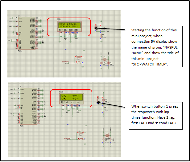
From the mini project, use PROTEUS to create a circuit of this mini project “STOPWATCH WITH LAP TIMES” and create coding using KEIL and run with Simplicity studio to run and burn the program C. Firstly, the circuit always have some basic error because got a little mistake when solder it. We use a Toolstick850 replace IC8051 because this Toolstick850 is easy then IC8051. Stopwatch basically plays with time minutes, second and miliseconds so the time should be running accurate. We got some error from a conversion programmer from KEIL to SIMPLICITY STUDIO, stand still we change some instructions on coding C. Basically, the 2 x 16 LCD works on 4-bit or 8-bit data line and three control lines. Now we use LCD for 4-bit because it’s easy to check the error. The control lines are RS, R/W and E. All communication between 2 x 16 LCD and host processor is synchronized by E line. For this Toolstick850 we change the connection port. Port LCD we use P0.0 to P0.7 in Toolstick850. The output can be in result as we keep this program.

CONCLUSION

The STOPWATCH has been using a system of "Proteus VSM software" to get the schematic diagram. Use code on Keil software uVision4 and Simplicity Studio. In addition, developing a code by using the output of 2x16 LCD unit using ic8051 develop tools for measuring analog equipment. STOPWATCH time tracking system for a setting that is programmed using coding C system. This STOPWATCH has been set to two rounds of LAB at coding and displayed by the LCD display. Each connection appearing in the circuit by using strips board because it is easier to identify the error that will occur. For STOPWATCH can learn how it works by using a microcontroller program.

REFERENCE

       I.            https://en.wikipedia.org/wiki/Stopwatch
    II.            http://www.silabs.com/Pages/default.aspx
 IV.            Note and refer From lecture ZULKHAIRI BIN MD YUSOF

Friday, 11 December 2015

STOPWATCH WITH LAPTIMES VIDEO

Produced by Hanif Razali and Nasrul Fadli.
Directed by Sir Zulkhairi.
                  Link Video Youtube

Coding In Simplicity Studio Software

//-----------------------------------------------------------------------------
// Includes
//-----------------------------------------------------------------------------
#include <SI_C8051F850_Register_Enums.h>
#include "InitDevice.h"
#include "stdio.h"

//-----------------------------------------------------------------------------
// Function PROTOTYPES
//-----------------------------------------------------------------------------

sbit SW0 = P2^1;
const unsigned int str[10];
int milisec,sec,minute;
char flag=0;
//-----------------------------------------------------------------------------
//------------lcd header----------------------------------------

sbit EN = P0^0;
sbit RW = P0^1;
sbit RS = P0^2;

#define DATA P0

void EN2HIGH(void);
void EN2LOW(void);
//void init_usart(void);
void Delay_MS(unsigned int x);
unsigned char check_busy(void);      //function declaration'
char read_data(void);
void send_control(char x);
void send_data(char x);
void Initialize_LCD(void);
void puts_lcd(char *pointer);

void puts_lcd(char *pointer){
     while(*pointer)     // print till null encountered
send_data(*pointer++);
}

void Delay_MS(unsigned int x){
unsigned int i, j;
for(i=0; i<x; i++){
for(j=0; j<20; j++);  //adjust delay faster
 }
}

unsigned char check_busy(void){
  RS = 0; // Logic ‘0’
  RW = 1; // Logic ‘1’
DATA|=0xf0;   // Set data line as input
  Delay_MS(1);
EN2HIGH();
if(DATA&0x80){
EN2LOW();
EN2HIGH();
EN2LOW();
DATA&=0x0f;   // Set data line as output
return 1;
}
else{
EN2LOW();
EN2HIGH();
EN2LOW();;
DATA&=0x0f;   // Set data line as output
return 0;
}
}

char read_data(void){
  char x;
  while(check_busy());

DATA|=0xf0;   // Set data line as input
  RS = 1; // Logic ‘1’
  RW = 1; // Logic ‘1’
  Delay_MS(1);
EN2HIGH();
x = DATA;
EN2LOW();
EN2HIGH();
x |= DATA>>4;
EN2LOW();
DATA&=0x0f;   // Set data line as output
return x;
}

void send_control(char x){
  while(check_busy());
DATA&=0x0f;   // Set data line as output
  RS = 0; // Logic ‘0’
  RW = 0; // Logic ‘0’

DATA&=0x0f;   // clear previous data
DATA |= x&0xf0;
  Delay_MS(1);
EN2HIGH();
EN2LOW();
DATA&=0x0f;   // clear previous data
DATA |= x<<4;
Delay_MS(1);
EN2HIGH();
EN2LOW();
}

void send_data(char x){
while(check_busy());
DATA&=0x0f;   // Set data line as output
  RS = 1; // Logic ‘0’
  RW = 0; // Logic ‘0’

DATA&=0x0f;   // clear previous data
DATA |= x&0xf0;
  Delay_MS(1);
EN2HIGH();
EN2LOW();
DATA&=0x0f;   // clear previous data
DATA |= x<<4;
Delay_MS(1);
EN2HIGH();
EN2LOW();
}

void Initialize_LCD(void){
DATA = 0x00; // Set data line as output
Delay_MS(20);     // 20ms @ 16MHz
send_control(0x33);
send_control(0x33);
send_control(0x32);
send_control(0x28); // 4 bit mode
send_control(0x10); // clear the screen
send_control(0x06);
send_control(0x0C);
send_control(0x01); // display on cursor on
send_control(0x06); // increment cursor
send_control(0x80); // row 1 column 1
}

void EN2HIGH(void){
EN=1;
  Delay_MS(1);
}

void EN2LOW(void){
EN=0;
Delay_MS(1);
}

//--------------------------delay---------------------------------

void delay_10us(unsigned int x){
unsigned int i;
for(i=0; i<x; i++);
 }


void delay_0dot1ms(unsigned int x){
unsigned int i, j;
for(i=0; i<x; i++){
 for(j=0; j<11; j++);
   }
 }

void delay_1ms(unsigned int x){
unsigned int i, j;
for(i=0; i<x; i++){
 for(j=0; j<1111; j++);
   }
 }
// MAIN Routine
//-----------------------------------------------------------------------------
void main (void){
   //Sysclk - 24.5Mhz/8 Timer2 overflow set to 1
   enter_DefaultMode_from_RESET();

   Initialize_LCD();

   send_control(0x80);
   puts_lcd("NASRUL HANIF");

   send_control(0xC0);
puts_lcd("STOP WATCH TIMER");

   while(SW0);
   delay_1ms(10);

send_control(0x01);
    delay_1ms(100);


while(1){

milisec++;
delay_1ms(50);

if (milisec>=10){
milisec=0;
sec++;
if (sec>=60){
sec=0;
minute++;
}
}

send_control(0x80);
sprintf(str,"    %d:%d:%d   ",minute,sec,milisec);
puts_lcd(str);

if (!SW0 && flag==0){
delay_1ms(100);
send_control(0xC0);
sprintf(str,"LAP1:    %d:%d:%d   ",minute,sec,milisec);
puts_lcd(str);
flag=1;

}

if (!SW0&&flag==1){
delay_1ms(100);
send_control(0x80);
sprintf(str,"LAP2:    %d:%d:%d   ",minute,sec,milisec);
puts_lcd(str);
milisec=sec=minute=0;
IE_EA = 0; //stop timer


while(SW0);
delay_1ms(100);   //debouncing
milisec=sec=minute=0;
flag=0;
send_control(0x01);
puts_lcd("");
IE_EA =1;  //start timer
}

}
}
//-----------------------------------------------------------------------------
// End Of File
//-----------------------------------------------------------------------------

Wednesday, 9 December 2015

STOPWATCH WITH LAP TIMES
Alhamdulilah, Our mini project have done tomorrow. As a proof of work done, We were attached some picture below.
Progress work on 9/12/2015
Connected To USB Port 
Displays Members Name and Project Name

Monday, 30 November 2015

BUY LCD AND DONAT BOARD

1. LM016L LCD 2X16
2. DONAT BOARD


THE PRICE OF LCD AND DONAT BOARD


Sunday, 22 November 2015

OBJECTIVE OF STOPWATCH WITH LAPTIMES

The objectives of this project:
#Build a fully functional stopwatch. 

THEORY OF PROJECT

The timer is really just a count down counter (i.e. it counts down to 0). When Reset is a “1” or if the counter value reaches 0, the counter gets reloaded with the preload value (supplied on the load number input port) and then begins counting back down to 0.

ce is the clock enable. Tying this to ’1’ or Vcc, will cause the timer to run continuously. 

clk is the clock input. It is connected to the system MCLK signal. 

reset is the reset signal. It is an active high reset and is asynchronous to the clock input. load number is a 24-bit input bus which supplies a preload value (see below) for the timer. 

zero is the zero output signal which is asserted when the count reaches 0. The zero signal is only asserted for one clock period of clk. 

tp is a test point for the programmable timer. 

The output is a square wave at 1/2 the frequency of the zero output. 

counter is a 24-bit output bus which gives the state of the 24 bits of the counter. It is only used for debugging purposes. The zero output will be connected to the Incr input of the Mod4 state machine you design in part I of this project.

Sample Video from the youtube.com


https://www.youtube.com/watch?v=1XZArZLvEg0

Thursday, 19 November 2015

PART 5: PROPOSAL WRITING

For proposal writing, after that we can make a research, identify and purchase the necessary components, now we make a proposal. In our proposal there is some info as follows:

1. Introduction
Special watches with buttons that start, stop, and then zero the hands, used to time races.  A stopwatch is a handheld timepiece designed to measure the amount of time elapsed from a particular time when activated to when the piece is deactivated. A large digital version of a stopwatch designed for viewing at a distance, as in a sports stadium, is called a stop clock.
Real-time functions traditionally controlled by two buttons on the case. Pressing the button on the timer starts to run errands, and press the button a second time to stop it, leave the elapsed time is displayed. A second later press the button to reset the stopwatch to zero. The second button is also used to record split times or lap times. When the split time button is pressed while the watch is running, the display freezes, allowing time to pass when it is read, but the watch mechanism continues running to record total elapsed time. Pressing the split button a second time allows the watch to resume display of total time.

2. Block diagram
3. Component
  • Silicon lab toolstickk850-b-sk
  • LCD Display 2x16
  • Strip board/donut board
  • Resistor
  • Capacitor
4. Input & Output
  • LCD display
  • Button switch on/off
  • Silicon labs